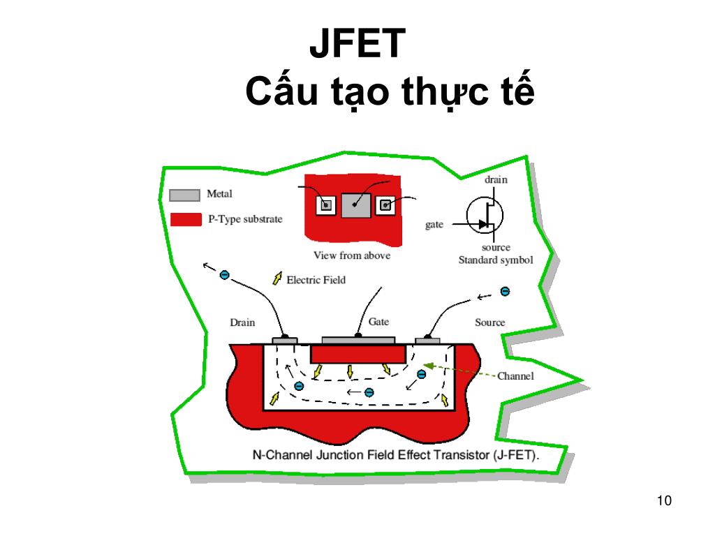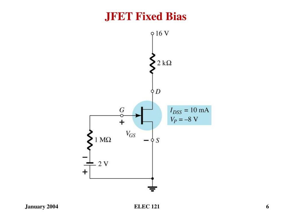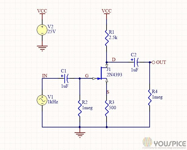

Choosing ID = 4 mA, VGS = -4mA×1 k = -4 v The line is drawn below: Solution: Step 1: Draw the self bias line: VGS = - IDRS, When ID = 0, VGS = 0. JFET Self Bias Circuit: Example 1 Determine the following: VGSQ, IDQ, VDS, VS, VG, and VD. JFET Self Bias Circuit DS Loop: Using KVL Substituting IS = ID, or In addition If ID = 0 then VGS = 0 and ID = IDDS/2 (say), then VGS = -IDDS RS /2 Superimposing this straight line on the transfer curve, we get Q-point as shown in the Fig. JFET Self Bias Circuit: Q-Point Transfer Curve (Shockley equation) Self-Bias Line: Since VGS = -IDRS. JFET Self Bias Circuit Shockley Equation: JFET Self Bias Circuit IG = 0 IS = ID From GS Loop: -VGS = VRS or VGS = -ISRS Substituting IS = ID VGS = -IDRS. Self Bias Circuit: DC Analysis Self-bias Circuit for dc analysis VGSQ (b) IDQ (c) VDS (d) VD (e) VG (f) VS.JFET Biasing: Fixed Bias Circuit Circuit for dc analysisĮxample: Determine the following for the given Fig. The following relations can be applied to the dc analysis of most of the FET amplifiers:.Plot the transfer characteristic curve from these data. Determine the values of ID for each value of VGS ranging from 0 v to -8 v in 1 v steps. Transfer curve from the drain characteristicsĮxample The following parameters are obtained from a certain JFET datasheet: VP = -8 v and IDSS = 5 mA. William Bradford Shockley derived a relationship between ID and VGS which is known as Shockley’s equation and is given by.The JFET must operate between VGS = 0 and VGS(off).

The value of VGS that makes ID approximately zero is the cutoff voltage VGS(off).


 0 kommentar(er)
